Custom components
Create brackets, housings, adapters, covers and other purpose-built parts around a specific requirement.
3D MODELING
Technical 3D and CAD modeling for mechanical parts, manufacturing and 3D printing from sketches, measurements, drawings, photographs or an idea.
PRINTURA
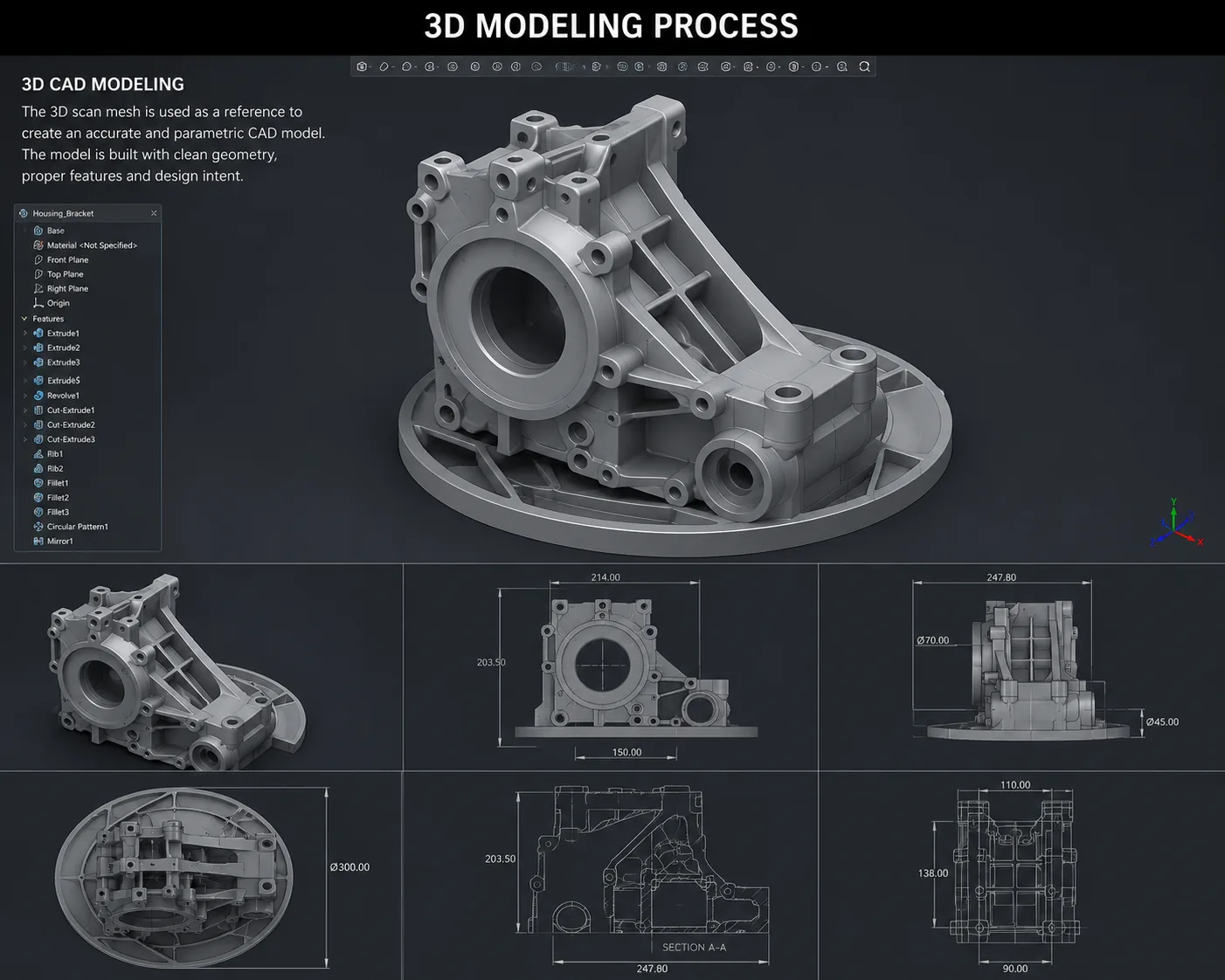
Technical 3D modeling bridges the gap between an idea and a CAD model that can be manufactured, 3D printed or used in a wider mechanical assembly. A project can start from sketches, dimensions, technical drawings, photographs, an existing component or a clear functional requirement.
The model is developed around its intended use. That may mean drawing-to-CAD conversion, a mechanical component, printable geometry, an existing-design revision or manufacturing-ready CAD for further engineering work. Critical dimensions, interfaces and production constraints are considered instead of treating the model only as a visual object.
COMMON APPLICATIONS
Create brackets, housings, adapters, covers and other purpose-built parts around a specific requirement.
Translate drawings, dimensions or sketches into a usable three-dimensional model.
Adjust existing geometry to change dimensions, interfaces, clearances or functional features.
Prepare parts for additive manufacturing when the starting idea or reference is not yet a production-ready model.
HOW IT WORKS
We review dimensions, sketches, photos, drawings, existing files and the functional requirements of the part.
The geometry is created and adjusted around the agreed dimensions, interfaces and intended manufacturing method.
The final model is checked and prepared for printing, manufacturing or the next stage of the project.
WHAT TO SEND
Useful inputs include sketches, drawings, measurements, reference photos, existing 3D files, mating-part dimensions and a short explanation of what the component needs to do.
FREQUENTLY ASKED QUESTIONS
Short answers to common questions about this service and how it can fit into a project.
Yes. Modeling can start from sketches, drawings, dimensions, reference photos, existing files or a clear functional description.
Yes. Dimensions, interfaces, clearances and functional features can be changed when the supplied geometry is suitable for the required work.
Yes. If the project is intended for additive manufacturing, the geometry can be developed with that production route in mind and then continue into the 3D-printing stage.
Critical dimensions, connection points, reference geometry, expected function and any limits around size or assembly are particularly useful. More context usually means fewer assumptions during modeling.
Yes. The focus is usable engineering geometry for mechanical parts, manufacturing, modification and 3D printing, with dimensions and interfaces considered around the intended function.